Premature bearing failure halts operations and destroys mechanical efficiency on the plant floor. Selecting the wrong bearing type leads to catastrophic equipment downtime, excessive heat generation, and compromised mechanical assemblies. Engineers constantly face a strict balancing act. They must manage load capacity, rotational speed, and spatial constraints within tight housing tolerances. Defaulting to the highest load capacity is a common design error. This approach often sacrifices rotational speed and increases system friction, leading to rapid lubricant degradation.
This guide provides a rigorous technical framework to evaluate a ball bearing vs roller bearing configuration. We strip away the guesswork, focusing on contact mechanics, load vectors, and kinematic limitations. You will learn how to match the exact rolling element to your operational demands, ensuring optimal performance and maximizing mechanical longevity for specific applications.
Contact Mechanics Dictate Performance: Ball bearings utilize point contact, minimizing friction for high-speed applications, whereas roller bearings use line contact to distribute heavy loads over a larger surface area.
Load vs. Speed Trade-off: Roller bearings excel under heavy radial and shock loads at modest speeds; ball bearings are the standard for high-RPM, low-to-medium load environments.
Misalignment Tolerances: Specific roller bearings (like spherical) handle shaft misalignment better than standard ball bearings, which is critical for heavy industrial machinery.
Table of Contents
Toggle
Fundamental Mechanics: Point Contact vs. Line Contact
The Physics of Ball Bearings
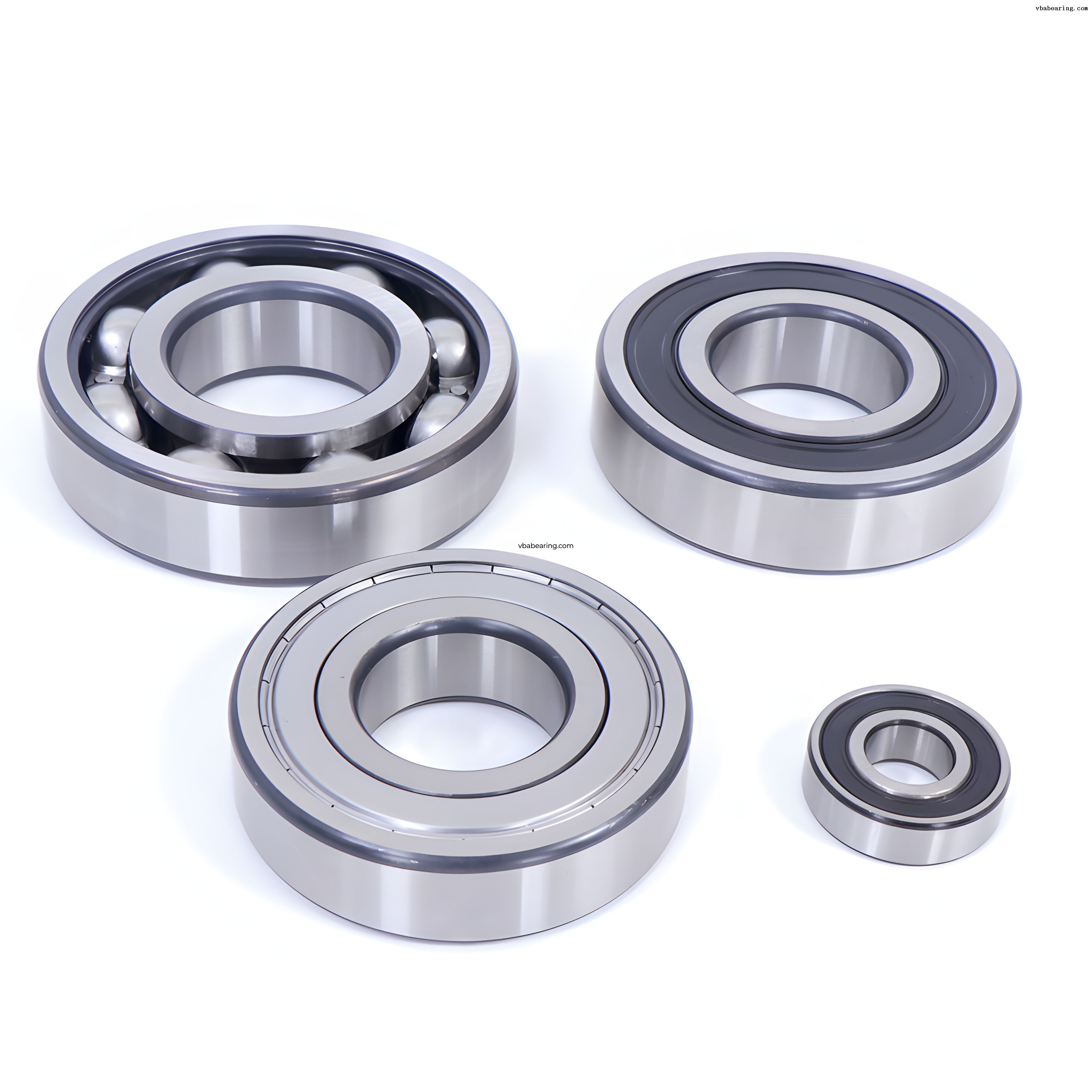
Ball bearings operate on the principle of point contact. The spherical rolling elements touch the inner and outer raceways at infinitely small points. Under physical load, this theoretical point flattens slightly into a microscopic elliptical contact area. This minimal contact surface is the defining mechanical feature of the bearing. It drastically reduces the surface area subjected to sliding friction during rotation.
This minimal friction produces a lower coefficient of friction overall. Less friction translates directly to reduced heat generation. Lower thermal output allows ball bearings to achieve significantly higher permissible rotational speeds. The internal geometry prevents the lubricant from overheating and breaking down rapidly. You will find this design standard in high-speed electric motors, machine tool spindles, and precision HVAC blowers.
Startup friction is another metric where this design excels. Ball bearings possess a significantly lower coefficient of friction at startup compared to roller bearings. Machinery requires less initial torque to begin rotation. The drive motors experience less electrical strain during the initial power phase. We specify ball bearings heavily in applications with frequent stop-start cycles to protect the electrical infrastructure.
Point contact presents a strict mechanical limitation. The reduced contact area concentrates mechanical stress into a very small zone on the raceway. When subjected to extreme heavy loads, this concentrated stress exceeds the yield strength of the 52100 bearing steel. The rolling elements will cause plastic deformation in the raceways, known as brinelling. This permanent indentation destroys the smooth rolling surface and causes immediate vibration issues.
The Physics of Roller Bearings
Roller bearings operate on the principle of line contact. They utilize cylindrical, tapered, or spherical rolling elements instead of balls. These elongated elements distribute the applied weight across a much broader surface area along the raceway. Under load, the theoretical line forms a rectangular contact zone. This geometry fundamentally changes how the bearing handles mechanical stress and shock impacts.
Line contact provides a massive mechanical advantage for load capacity. Roller bearings deliver significantly higher static and dynamic load ratings. They can support immense radial forces without deforming the raceway material. The broader surface area keeps the internal Hertzian contact stress levels well below the yield point of the steel. We rely on them for heavy machinery, industrial gearboxes, and aggregate crushers.
This load capacity comes with a direct operational trade-off. The increased contact area inherently results in higher rolling friction. Higher friction generates more thermal energy during rotation. The bearing must dissipate this excess heat to prevent lubrication failure and thermal expansion of the rolling elements. Consequently, roller bearings have a much lower maximum operational speed compared to ball bearings of similar dimensions.
Edge loading is a specific failure mode unique to line contact. If the shaft deflects or misaligns, the rectangular contact patch skews. The load concentrates heavily on the extreme edges of the roller. This edge loading fractures the lubricant film and causes rapid metal-to-metal wear. Engineers must ensure high housing rigidity and precise shaft alignment when specifying standard cylindrical rollers.
Core Performance Metrics
Load Capacity and Directional Forces
Understanding load vectors is the first step in any bearing comparison. Radial loads act perpendicularly to the rotating shaft. Ball bearings offer moderate radial capacity suitable for light to medium applications. Cylindrical roller bearings provide exceptional radial capacity. Their line contact absorbs massive perpendicular forces without compromising structural integrity.
Axial loads, or thrust loads, act parallel to the shaft. Angular contact ball bearings are engineered to handle combined radial and axial loads simultaneously. Their asymmetric raceways transfer the load at a specific contact angle. Tapered roller bearings are vastly superior for heavy combined loads. Their conical geometry manages severe radial and thrust forces in applications like vehicle wheel hubs and heavy-duty transmissions.
Shock loads introduce sudden, high-impact forces into the mechanical system. Roller bearings are structurally superior for absorbing these impacts. The broad line contact dissipates the sudden energy spike across a wide area. Ball bearings struggle with shock loads. A sudden impact forces the ball into the raceway, causing permanent brinelling that ruins the assembly.
Bearing Type
Radial Load Capacity
Axial Load Capacity
Shock Load Resistance
Deep Groove Ball
Moderate
Low
Poor
Angular Contact Ball
Moderate
High (One Direction)
Poor
Cylindrical Roller
Extreme
Very Low
Excellent
Tapered Roller
High
High (One Direction)
Excellent
Spherical Roller
Extreme
Moderate
Excellent
Speed and Rotational Limits
High-speed kinematics dictate bearing selection in fast-rotating machinery. Ball bearings excel at high RPMs due to their low mass and minimal friction. The spherical elements generate less centrifugal force as they travel around the raceway. This reduces the outward pressure exerted on the outer ring. High-speed applications often utilize specialized machined brass or lightweight polyamide cages to maintain ball separation and reduce drag.
Roller bearings face strict kinematic limitations at high speeds. The heavier rolling elements generate significant centrifugal force. This force pushes the rollers aggressively against the outer raceway and the cage. Cage design becomes a limiting factor. The cage must withstand the sliding friction and heavy mass of the rollers. This friction rapidly degrades the lubricant at elevated speeds, leading to thermal runaway.
Thermal dynamics play a critical role in rotational limits. Heat dissipation requirements scale differently for point versus line contact. Ball bearings generate less heat and reach thermal equilibrium faster. Roller bearings generate substantial heat at peak operational speeds. If the system cannot dissipate this heat, the internal clearances vanish. The rolling elements expand, consume the radial play, and the bearing seizes onto the shaft.
Noise, Vibration, and Harshness (NVH)
Acoustic performance is vital for specific engineering applications. Ball bearings generally run quieter and smoother than roller bearings. The point contact creates minimal surface disruption during rotation. The manufacturing process can achieve extremely tight tolerances on spherical elements. This precise geometry makes ball bearings ideal for precision instruments, medical devices, and electric motors where NVH must be minimized.
Roller bearings produce a different acoustic profile under load. The line contact generates more surface interaction and audible noise. Slight variations in roller diameter or raceway alignment can introduce vibration. In heavy industrial applications, NVH is a secondary concern. Engineers prioritize durability and load capacity over quiet operation. The inherent noise of a roller bearing is acceptable in mining, paper mills, or construction equipment.
Vibration analysis reveals distinct frequency signatures for each type. Ball bearings typically exhibit higher frequency, lower amplitude vibrations. Roller bearings generate lower frequency, higher amplitude vibrations due to the larger mass of the rolling elements striking the load zone. Maintenance teams use these specific frequencies to diagnose raceway defects before catastrophic failure occurs.
Evaluating Ball Bearing Variants for Specific Outcomes
Deep Groove Ball Bearings
Deep groove ball bearings are the most versatile and common type in the industry. They feature deep, uninterrupted raceway grooves that closely conform to the balls. This design allows them to support moderate radial loads and light axial loads in both directions. They are simple in design, non-separable, and require minimal maintenance once installed correctly.
These bearings dominate applications requiring high speeds and reliable operation. You will find them in electric motors, household appliances, and light automotive applications. Engineers often specify them with integrated seals (2RS) or metal shields (ZZ) to retain grease and block contaminants. Internal clearance designations, like C3 or C4, allow engineers to account for thermal expansion in high-heat environments.
Angular Contact Ball Bearings
Angular contact ball bearings feature an asymmetric cross-section. The inner and outer ring raceways are displaced relative to each other in the direction of the bearing axis. This geometry is specifically designed to accommodate simultaneous radial and axial loads. The axial load carrying capacity increases directly as the contact angle increases. Common contact angles range from 15 to 40 degrees.
These bearings are essential when rigid axial guidance is required. Ideal use cases include machine tool spindles, agricultural equipment, and high-performance centrifugal pumps. Engineers typically mount them in pairs or sets. We use back-to-back (DB), face-to-face (DF), or tandem (DT) arrangements. These configurations accommodate axial forces in both directions and provide high system rigidity against overturning moments.
Thrust Ball Bearings
Thrust ball bearings are designed exclusively for pure axial loads. They consist of shaft washers, housing washers, and a ball and cage assembly. They cannot support any radial loads whatsoever. They are manufactured as single-direction or double-direction bearings depending on the application requirements. The housing washers often feature a sphered seating surface to compensate for initial mounting inaccuracies.
These bearings operate best at moderate speeds. Centrifugal forces at high speeds cause the balls to skid outward against the raceway groove. This skidding fractures the lubricant film and causes rapid smearing damage. Ideal use cases include fluid control valves, low-speed automotive steering mechanisms, and rotary tables. They provide excellent axial support in highly constrained vertical spaces.
Evaluating Roller Bearing Variants for Heavy-Duty Outcomes
Cylindrical Roller Bearings
Cylindrical roller bearings offer the maximum possible radial load capacity for a given cross-section. The rollers are guided by flanges on either the inner or outer ring. This design provides exceptional stiffness and low friction. They are typically used where heavy radial loads and high speeds are combined, such as large electric motors and traction generators.
They have very limited axial load capabilities. Standard designs (N and NU types) allow the shaft to expand axially without restriction. Variants with flanges on both rings (NJ and NUP types) can accommodate slight axial forces. Ideal use cases include conveyor belt rollers, heavy industrial gearboxes, and large industrial pumps. They are designed to be separable, making mounting and dismounting easier in tight interference fits.
Tapered Roller Bearings
Tapered roller bearings utilize conical rollers guided by a backing flange on the cone. This specific conical geometry is engineered to manage severe combined radial and axial loads. The projection lines of the raceways meet at a common point on the bearing axis. This ensures true rolling motion and low friction along the entire length of the roller.
These bearings are highly resilient under harsh conditions. They are the standard choice for automotive wheel bearings, heavy truck axles, and aerospace components. Engineers usually mount them in opposed pairs. This setup allows the bearings to handle thrust loads from either direction. Mechanics must manually set the internal clearance or preload during installation by adjusting the axial distance between the two bearings.
Spherical Roller Bearings
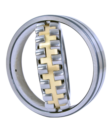
Spherical roller bearings feature two rows of barrel-shaped rollers. They operate on a common sphered outer ring raceway. This unique design provides inherent self-aligning capabilities. The bearing can accommodate significant shaft deflection and mounting errors without increasing internal friction or reducing lifespan. They handle misalignment up to 2 degrees without issue.
This self-aligning feature is critical in heavy industrial applications. The bearing mitigates edge loading caused by bending shafts under extreme loads. Ideal use cases include massive mining equipment, paper mill rollers, and offshore wind turbines. They handle extreme radial loads and moderate axial loads in the harshest environments imaginable. We frequently specify them with brass cages for maximum vibration resistance.
Needle Roller Bearings
Needle roller bearings utilize cylindrical rollers with a very high length-to-diameter ratio. Despite their small cross-section, they provide an exceptionally high load-carrying capacity. They are designed specifically for applications with highly constrained radial spaces. The thin rollers minimize the overall outer diameter of the bearing assembly, allowing for compact gearbox designs.
These bearings are highly sensitive to shaft misalignment. They require hardened and ground shafts if operated without an inner ring. The shaft itself acts as the inner raceway, requiring a surface hardness of HRC 58-64. Ideal use cases include automotive transmissions, air compressors, and planetary gear sets. They deliver maximum radial support in the smallest possible physical envelope.
Roller Variant
Primary Load Type
Misalignment Tolerance
Space Requirement
Cylindrical
Pure Radial
Very Low
Moderate
Tapered
Heavy Combined
Low
Moderate
Spherical
Extreme Radial
High (Self-Aligning)
Large
Needle
High Radial
Very Low
Minimal (Compact)
Engineering Decision Framework
Defining Success Criteria for Your Application
Engineers must define strict success criteria before selecting a bearing. You must calculate the equivalent dynamic bearing load accurately. This calculation determines the required L10 life. The L10 life represents the number of operating hours that 90% of a bearing group will complete before the first signs of metal fatigue appear on the raceways or rolling elements.
The mathematical difference in the life equation is critical. The equation is $L_{10} = (C/P)^p$. For ball bearings, the exponent is $p=3$. For roller bearings, the exponent is $p=10/3$. This means roller bearings are significantly more resilient to load increases. A small increase in load drastically reduces the lifespan of a ball bearing. You must project these lifespans under varying operational loads to ensure mechanical reliability.
Environmental factors dictate the final specification. You must assess temperature extremes. High temperatures degrade standard lubricants and reduce steel hardness. Contamination risks require specific sealing mechanisms. Heavy dust or water ingress destroys internal rolling surfaces rapidly. You must match the bearing seals, shields, and lubrication type to the exact environmental hazards present on the site.
Maintenance and Longevity Considerations
Maintenance demands vary significantly between bearing types. You must compare lubrication requirements carefully. Ball bearings often operate flawlessly on standard grease lubrication for extended periods. The low friction generates less heat, preserving the grease structure. Many deep groove ball bearings are sealed for life and require zero relubrication, simplifying maintenance schedules.
Roller bearings often demand more rigorous lubrication protocols. The line contact generates higher friction and heat. Heavy-duty roller bearings frequently require circulating oil baths or oil mist systems to dissipate heat and flush away wear particles. You must analyze replacement frequency and downtime. Specifying a heavy-duty tapered roller bearing extends maintenance intervals significantly compared to a standard ball bearing under the same load.
Grease packing volume is a critical installation factor. Overpacking a bearing with grease causes rapid thermal runaway. The rolling elements churn the excess lubricant, generating massive fluid friction. The temperature spikes, the oil separates from the thickener, and the bearing seizes. We strictly adhere to a 30% to 40% fill rule for high-speed applications to prevent this failure.
Implementation Risks and Real-World Design Mitigation
Housing and shaft rigidity are paramount. The choice of bearing directly impacts the surrounding assembly design. Roller bearings require highly rigid housings and thick shafts. Any deflection causes the rollers to press unevenly against the raceway. This edge loading destroys the bearing rapidly. Ball bearings are slightly more forgiving of minor deflections due to their point contact.
Misalignment is a severe implementation risk. Cylindrical roller bearings will fail quickly if the shaft is misaligned. The line contact cannot accommodate the skewed angle. You must mitigate this risk during the design phase. If shaft deflection is unavoidable due to heavy overhung loads, you must specify self-aligning spherical roller bearings to absorb the geometric errors.
Minimum load requirements are frequently overlooked. Roller bearings must operate under a specific minimum load to function correctly. If operated below this threshold, the rollers will not roll. They will skid and smear across the raceway. This smearing causes rapid surface damage and micro-welding. You must ensure the application provides enough resistance to keep the rollers turning at all times.
Space constraints force difficult engineering compromises. You must evaluate the radial cross-section trade-offs. If radial space is severely limited, a deep groove ball bearing may not fit. You must transition to a needle roller bearing. The needle bearing provides the necessary radial load capacity while fitting into the constrained housing envelope, though it requires stricter shaft hardness specifications.
Conclusion
Map all load vectors accurately to determine the exact ratio of radial to axial forces acting on the shaft.
Calculate the equivalent dynamic bearing load and determine the required L10 life using the correct exponent for your chosen rolling element.
Define your absolute RPM limits and evaluate the frequency of startup cycles to select the appropriate cage material and lubrication type.
Assess your spatial limitations, housing rigidity, and potential shaft deflection to determine if self-aligning capabilities are required.
Verify shaft and housing tolerances to ensure proper interference fits, preventing fretting corrosion and ring creep during operation.
FAQ
Q: Which has a higher coefficient of friction: ball bearings or roller bearings?
A: Roller bearings generally have higher running friction due to line contact. The broader surface area creates more drag. Ball bearings have lower friction due to point contact. Ball bearings also have a notably lower coefficient of friction at startup, requiring less initial torque from the drive motor.
Q: Can roller bearings handle axial (thrust) loads?
A: Standard cylindrical roller bearings handle very little axial load. However, tapered roller bearings and spherical roller bearings are specifically designed for heavy combined radial and axial loads. They use specialized internal geometry and conical rollers to manage thrust forces effectively.
Q: Why are ball bearings quieter than roller bearings?
A: The point contact of ball bearings creates less surface friction and material deformation during rotation. This precise, minimal contact results in lower acoustic emissions and less vibration. This makes them ideal for electric motors, HVAC blowers, and precision instruments requiring low noise.
Q: What is the lifespan difference between ball and roller bearings?
A: Lifespan depends entirely on application sizing and the L10 life calculation. This calculation scales differently for each type. Under heavy loads, a roller bearing will vastly outlast a ball bearing. Under high speeds with light loads, a ball bearing will survive longer without overheating.
Q: Can I directly replace a ball bearing with a roller bearing?
A: Rarely without modification. While they may share dimensional envelopes like bore and outer diameter, their operating characteristics differ wildly. The difference in friction, heat generation, housing rigidity requirements, and load distribution usually requires a re-evaluation of the entire mechanical assembly.
Q: What happens if you put a ball bearing in a high-load application?
A: The point contact will experience excessive mechanical stress. This concentrated pressure leads to plastic deformation of the raceway, known as brinelling. This causes rapid heat buildup, severe vibration, and premature catastrophic failure of the bearing assembly.

 English
 العربية
 Français
 Русский
 Español
 Português
 Deutsch
 italiano
 日本語
日本語 한국어
한국어 Nederlands
 Tiếng Việt
 ไทย
ไทย Polski
 Türkçe
 ພາສາລາວ
 ភាសាខ្មែរ
 Bahasa Melayu
 ဗမာစာ
ဗမာစာ தமிழ்
தமிழ் Filipino
 Bahasa Indonesia
 magyar
 Română
 Čeština
 Монгол
 қазақ
қазақ Српски
 हिन्दी
 فارسی
فارسی Kiswahili
 Slovenčina
 Slovenščina
 Norsk
Norsk Svenska
 українська
 Ελληνικά
 Suomi
Suomi Հայերեն
 עברית
עברית Latine
 Dansk
Dansk اردو
اردو Shqip
Shqip বাংলা
বাংলা Hrvatski
 Afrikaans
 Gaeilge
 Oʻzbekcha
 Български
 ქართული