Mechanical failure in heavy-duty applications carries severe consequences. When industrial gearboxes, rolling mills, or wheel hubs fail, unplanned downtime immediately halts production lines and disrupts operational schedules. The root cause of these catastrophic failures often traces back to the initial design phase. Specifically, miscalculating load dynamics, ignoring environmental stressors, or setting improper tolerances leads to premature raceway spalling, compromised system rigidity, and excessive maintenance interventions. Engineers must account for dynamic forces, thermal expansion, and exact installation parameters to ensure the mechanical system reaches its intended lifecycle.
This guide provides a systematic, engineering-first framework for evaluating and specifying the correct rotating components. By moving beyond basic dimensions to assess load ratings, material science, and implementation realities, you can engineer reliability directly into the application.
Load Profiling is Non-Negotiable: Accurate calculation of combined radial and axial loads, as well as load directionality, dictates the required contact angle and bearing configuration.
Configuration Dictates Capability: The choice between single, double, or four-row designs fundamentally alters space requirements, load distribution, and system rigidity.
Installation Risks Define Lifespan: Improper setting techniques (end-play vs. preload) and incorrect shaft/housing fits account for a significant percentage of early bearing failures.
Table of Contents
Toggle
Framing the Selection Problem: Success Criteria for Bearing Selection
Establishing the baseline operational requirements is the first technical hurdle. Engineers must define the target L10 or L10m life expectancy. This metric represents the number of operating hours that 90% of a group of identical components will exceed before the first evidence of metal fatigue develops. Factoring in duty cycles, variable speed profiles, and reliability targets ensures the chosen component aligns with the machine's expected service life. A continuous-duty mining conveyor requires a vastly different reliability target than an intermittently operated agricultural implement.
Application Type
Typical Duty Cycle
Recommended L10 Life (Hours)
Agricultural Machinery
Intermittent / Seasonal
3,000 - 6,000
Automotive Wheel Hubs
Variable / Daily
150,000 - 250,000 (Miles)
Industrial Gearboxes
Continuous / Heavy Load
20,000 - 30,000
Paper Mill Rolls
Continuous / 24/7 Operation
100,000+
The physical envelope dictates the boundaries of bearing selection. You must balance the required shaft sizes (bore) and housing limits (outside diameter) with the necessary width to achieve the target load ratings. Space is heavily constrained in modern machinery. If the shaft diameter is dictated by torsional strength requirements, the remaining annular space determines the maximum possible roller size and the maximum load capacity. When the physical envelope restricts standard sizing, engineers must evaluate higher-capacity designs or alternative metallurgical profiles.
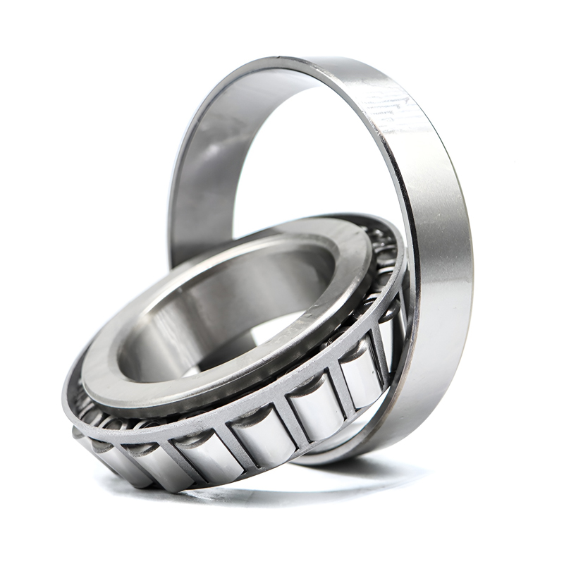
Tapered designs offer distinct mechanical advantages over cylindrical or spherical alternatives. The conical geometry of the inner ring (cone), outer ring (cup), and rollers allows these components to manage simultaneous high radial and axial loads. The projection lines of all the tapered surfaces meet at a common point on the central axis, ensuring true rolling motion and minimizing friction along the roller body. This geometry makes them exceptionally well-suited for applications where heavy thrust loads accompany standard radial forces.
The selected component heavily influences overall shaft rigidity, gear mesh accuracy, and vibration levels. High system rigidity prevents shaft deflection under heavy loads, maintaining precise gear contact patterns in transmissions. Unlike spherical designs that accommodate inherent misalignment, tapered configurations have strict alignment tolerances. Excessive shaft deflection or housing misalignment causes edge loading, where the stress concentrates at the ends of the rollers. This stress concentration rapidly breaks down the lubricant film and causes premature raceway failure.
Analyzing Load Capacity and Directional Forces
Radial vs. Axial Load Requirements
Accurate load profiling requires mapping the exact magnitude and direction of operational loads. Engineers must resolve all external forces—including gear forces, belt tensions, and gravitational weights—into their radial and axial components at the support locations. This vector resolution determines the actual forces the rolling elements must support during operation.
Directionality dictates the required assembly. Single-direction axial loads allow for the use of a standard single-row unit. Alternating or bidirectional thrust forces require paired assemblies or double-row configurations to support the load regardless of which way the shaft shifts. In applications like automotive wheel hubs, cornering forces create bidirectional axial loads that must be managed by opposing rows of rollers.
The relationship between the cup angle (contact angle) and thrust capacity is a primary selection factor. The contact angle typically ranges from 10 to 30 degrees. Steeper angles yield significantly higher axial load capacity but proportionally lower radial capacity. For applications dominated by heavy thrust, such as worm gear drives or propeller shafts, a steep-angle design is mandatory. For applications with heavy radial loads and moderate thrust, a shallow angle provides the optimal balance.
Dynamic vs. Static Load Ratings
The basic dynamic load rating (C) is the primary metric for calculating fatigue life under continuous rotation. It represents the constant radial load that a component can theoretically endure for a rating life of one million revolutions. Engineers use the dynamic load rating in conjunction with the application's equivalent load to determine the L10 life. This calculation ensures the component will not fail from subsurface material fatigue under normal operating conditions.
The basic static load rating (C0) evaluates the component's ability to withstand heavy stationary loads or sudden shock impacts without suffering permanent plastic deformation. If the static load exceeds the C0 rating, the rollers will indent the raceways. This deformation, known as brinelling, causes severe vibration and rapid failure once rotation resumes. Applications involving heavy presses, crushers, or highly loaded stationary shafts require careful static load evaluation.
Real-world applications rarely subject components to pure radial or pure axial forces. Engineers must calculate the equivalent dynamic bearing load (P), a single hypothetical load value that would have the same influence on fatigue life as the actual combined loads. Using manufacturer-specific X (radial) and Y (thrust) factors, the radial and axial forces are mathematically combined to determine the equivalent load used in the final L10 life equation.
Evaluating Tapered Roller Bearing Configurations
Single-Row (TS)
The single-row configuration is the standard choice for applications requiring basic combined load support. It consists of a single cone assembly and a single cup. These units are highly efficient in managing radial loads and axial loads in one direction simultaneously. They are the foundational building block for most rotating equipment designs.
Because they only support axial loads in a single direction, single-row units must be mounted in opposing pairs to manage bidirectional axial forces and establish shaft stability. Engineers specify either a face-to-face (DF) or back-to-back (DB) arrangement. A back-to-back arrangement provides a wider effective spread, making it vastly superior for handling overturning moments. The primary trade-off is the reliance on precise manual setting during assembly. Technicians must adjust the axial position of one unit relative to the other to achieve the required operating clearance or preload.
Double-Row (TDO/TDI)
Double-row configurations combine two single-row assemblies into a single unit. The TDO (Tapered Double Outer) design uses a double cup and two single cones, while the TDI (Tapered Double Inner) design uses a double cone and two single cups. These are heavily utilized in heavy-duty applications like industrial gear drives, rolling mills, and large pumps requiring high load capacity within a compact axial space.
The main operational advantage is the pre-set internal clearance. Manufacturers grind the spacer rings to exact dimensions, eliminating the need for manual clearance adjustment during installation. This reduces installation complexity and assembly time on the factory floor. This pre-set nature limits on-the-fly adjustability. If the application parameters change, the spacer must be physically reground or replaced to alter the internal clearance.
Four-Row (TQO)
Four-row configurations provide maximum load density. They are engineered specifically for extreme load environments, primarily serving as roll neck supports in heavy metal rolling mills. These units manage massive radial loads at low to moderate speeds, supporting the immense pressures required to reduce steel or aluminum slabs into thin sheets.
While they offer unparalleled load capacity, four-row assemblies introduce significant complexity. They require specialized lubrication systems to ensure oil or grease reaches the innermost rows of rollers. Mounting and dismounting procedures are highly complex. Technicians often use hydraulic nuts and specialized extraction tooling to handle the massive interference fits required on mill roll necks. In some designs, the bore features a spiral groove to allow lubricant to act as a hydraulic removal aid.
Configuration
Primary Use Case
Axial Load Direction
Installation Complexity
Single-Row (TS)
Standard combined loads, automotive hubs, light gearboxes
Single direction (requires pairing)
High (requires manual setting of end-play/preload)
Double-Row (TDO/TDI)
Heavy industrial drives, rolling mills, crane sheaves
Bidirectional
Low to Medium (pre-set clearances via spacers)
Four-Row (TQO)
Extreme radial loads, roll necks in metal rolling mills
Bidirectional
Very High (requires specialized hydraulic tooling)
Operating Environment and Material Specifications
Temperature Extremes and Thermal Expansion
Operating temperatures directly affect steel metallurgy and dimensional stability. Standard bearing steel undergoes a phase transformation if exposed to temperatures exceeding 120°C (250°F) for prolonged periods. The retained austenite in the steel transforms into martensite, causing the components to permanently expand and alter the internal clearances. For high-temperature applications, engineers must specify dimensionally stabilized rings that have undergone specialized tempering processes to prevent this metallurgical shift.
Thermal expansion impacts the operating clearance and preload. As machinery heats up, the shaft and housing expand at different rates depending on their materials and mass. A shaft that runs hotter than the housing will expand outward, potentially reducing the internal clearance to zero and causing a catastrophic thermal runaway. Calculating the thermal gradients across the assembly is mandatory to determine the correct cold-setting parameters.
Contamination and Sealing Solutions
Particulate and moisture ingress destroy rolling elements faster than fatigue. In harsh environments like mining, agriculture, and aggregate processing, abrasive dust mixes with the lubricant to form a lapping compound. This compound rapidly wears down the raceways and roller profiles, destroying the internal geometry and leading to excessive runout.
Evaluating sealing solutions requires comparing integrated seals versus external housing seals. Integrated seals save axial space and provide immediate protection, but they have speed limitations due to seal lip friction and heat generation. External housing seals, such as labyrinth or taconite seals, require more space but offer superior protection in highly contaminated environments. Taconite seals utilize a combination of felt rings, labyrinth paths, and a grease purge system to physically push contaminants away from the rotating assembly without adding friction.
Material Grades and Heat Treatment
Case-carburized steel is the standard for heavy industrial use. This heat treatment process creates a hard, wear-resistant outer layer while maintaining a tough, ductile core. This metallurgical profile excels at absorbing heavy shock loads and resisting crack propagation. If debris dents the raceway, the ductile core prevents the dent from rapidly developing into a deep fracture.
Through-hardened steel provides a uniform hardness from the surface to the core. It is highly suitable for consistent, high-cycle applications where surface fatigue is the primary failure mode, and shock loads are minimal. Through-hardened components offer excellent resistance to rolling contact fatigue but are more susceptible to cracking under severe impact loads compared to case-carburized alternatives.
Speed, Lubrication, and Friction Management
Speed Ratings and Thermal Limits
Speed capabilities are dictated by heat generation and heat dissipation. The thermal reference speed represents the rotational speed at which the heat generated by the rolling elements equals the heat dissipated through the shaft and housing under standard conditions. Operating above this speed requires specialized cooling systems to prevent the lubricant from degrading.
The limiting speed is the absolute mechanical limit determined by the cage design, centrifugal forces, and lubricant type. Exceeding the limiting speed causes cage fracture or lubricant film breakdown, leading to immediate failure regardless of the cooling capacity. Engineers must evaluate both speed ratings to ensure safe continuous operation.
Cage and Retainer Selection
The cage separates the rollers, prevents them from rubbing against each other, and retains them on the cone during installation. Cage material directly impacts maximum operational speeds, vibration tolerance, and lubrication retention. Stamped steel cages are the default for standard applications, offering a good balance of strength and open space for lubricant flow.
Machined brass cages are specified for applications involving high vibration, heavy shock loads, or high speeds. Brass provides excellent emergency running characteristics and structural integrity under severe acceleration. For extreme heavy-duty environments, particularly large-bore components, pin-type cages are utilized. These cages run a pin through the center of each roller, allowing for a maximum number of rollers to increase load capacity while maintaining robust separation.
Lubrication Strategies
Grease lubrication is the standard for low-to-medium speed applications. It simplifies housing design by acting as a supplementary seal against contamination. When specifying grease, engineers must evaluate the base oil viscosity at operating temperature, the thickener type, and the required maintenance intervals for relubrication. Over-greasing causes churning, which generates excessive heat and degrades the lubricant.
Oil lubrication is required for high-speed or high-temperature applications. Circulating oil systems actively remove heat from the contact zones, filter out wear particles, and ensure a continuous supply of fresh lubricant. Splash systems are simpler but require careful oil level management to prevent churning or starvation.
Elastohydrodynamic Lubrication (EHL) principles govern the separation of the rollers and raceways. The lubricant must form a microscopic film under extreme pressure to prevent metal-to-metal contact. Calculating the kinematic viscosity ratio ensures the chosen oil or grease provides adequate film thickness at the specific operating speed and temperature.
Implementation Risks: Setting Techniques and Tolerances
End-Play vs. Preload Settings
The final operational setting dictates the system's lifespan. End-play refers to a measurable axial clearance within the assembly, allowing a microscopic amount of free movement. Preload refers to a negative clearance, where the rollers are actively compressed against the raceways even when no external load is applied. Preload maximizes system rigidity and ensures all rollers share the load equally.
The risks of improper setting are severe. Over-preloading generates excessive friction, leading to rapid heat buildup, thermal expansion, and catastrophic spalling of the raceways. Excessive end-play allows the shaft to run out of alignment. This causes the rollers to skew off their intended path, leading to severe edge loading and rapid cage wear.
To achieve the correct setting, technicians utilize specific measurement procedures:
Mount the dial indicator base to the stationary housing.
Position the indicator tip against the end of the rotating shaft.
Oscillate the shaft while applying heavy axial force in one direction to seat the rollers.
Zero the dial indicator.
Apply heavy axial force in the opposite direction while oscillating the shaft.
Read the total indicator runout to determine the exact end-play.
Mounting and Dismounting Procedures
Installation errors account for a massive percentage of premature failures. Using excessive force, such as striking the rings directly with a hammer, causes immediate brinelling of the raceways. Improper tooling that applies force through the rolling elements rather than directly to the press-fit ring will destroy the internal geometry before the machine ever runs.
Following manufacturer torque recommendations for locknuts and utilizing proper thermal mounting techniques are mandatory. Induction heaters expand the inner ring safely and evenly, allowing it to slide onto the shaft without mechanical force. Technicians must heat the cone to approximately 120°C (250°F). Exceeding 150°C (300°F) alters the metallurgy and ruins the component. Once cooled, it achieves the precise interference fit required without risking microscopic fractures or scoring the shaft.
Shaft and Housing Fits
Selecting the proper tolerance classes ensures the rings are supported correctly by the machine components. The fit determines whether the rings will creep under load. Creep causes severe fretting wear, destroying the shaft journals and housing bores.
Generally, the rotating ring requires a tight interference fit to prevent creep, while the stationary ring requires a slightly loose transition fit to allow for axial adjustment during the setting process. Specifying the exact micrometer tolerances for the shaft and housing machining is just as critical as selecting the tapered roller bearing itself.
Conclusion
Calculate the equivalent dynamic load using your system's maximum radial and axial forces to establish a baseline requirement.
Measure your shaft and housing dimensions to determine the available physical envelope and restrict your selection to viable outside diameters and widths.
Select the appropriate contact angle based on your thrust-to-radial load ratio to ensure the geometry matches the directional forces.
Specify the required ISO tolerance classes for your shaft and housing machining to prevent fretting wear and allow for proper axial setting.
Establish a strict thermal mounting protocol using induction heaters to eliminate mechanical impact damage during assembly.
FAQ
Q: How do you calculate the required load capacity for a tapered roller bearing?
A: You calculate the required capacity by resolving all external forces into radial and axial loads. Using manufacturer-specific X and Y factors, you combine these into an equivalent dynamic load. This value is used alongside the basic dynamic load rating to calculate the L10 fatigue life, ensuring it meets operational targets.
Q: What is the difference between a single-row and double-row tapered roller bearing?
A: A single-row unit supports radial loads and axial loads in only one direction, requiring a paired opposing unit for stability. A double-row unit combines two rows into a single assembly, supporting heavy radial loads and bidirectional axial loads, often featuring pre-set internal clearances to simplify installation.
Q: How does the contact angle affect performance?
A: The contact angle dictates the ratio of radial to axial load capacity. A steeper angle significantly increases the axial thrust load capacity but reduces the radial load capacity. Shallow angles are preferred for heavy radial loads, while steep angles are necessary for high-thrust applications.
Q: How does shaft misalignment affect the system?
A: These designs have very low tolerance for misalignment. Excessive shaft deflection or housing misalignment causes the rollers to skew, leading to edge loading. This concentrates stress at the ends of the rollers, breaking down the lubricant film and causing rapid raceway spalling and premature failure.
Q: What happens if the assembly is over-preloaded during installation?
A: Over-preloading eliminates all internal clearance and forces the rollers too tightly against the raceways. This generates excessive friction and heat, leading to thermal expansion that further increases the preload. This thermal runaway rapidly destroys the lubricant and causes catastrophic spalling of the steel surfaces.
Q: Which lubrication method is best for high-speed applications?
A: Circulating oil systems are best for high-speed applications. Unlike grease, which can cause churning and retain heat at high velocities, circulating oil actively dissipates heat from the contact zones, flushes out microscopic wear particles, and maintains the required elastohydrodynamic film thickness under extreme rotational speeds.

 English
 العربية
 Français
 Русский
 Español
 Português
 Deutsch
 italiano
 日本語
日本語 한국어
한국어 Nederlands
 Tiếng Việt
 ไทย
ไทย Polski
 Türkçe
 ພາສາລາວ
 ភាសាខ្មែរ
 Bahasa Melayu
 ဗမာစာ
ဗမာစာ தமிழ்
தமிழ் Filipino
 Bahasa Indonesia
 magyar
 Română
 Čeština
 Монгол
 қазақ
қазақ Српски
 हिन्दी
 فارسی
فارسی Kiswahili
 Slovenčina
 Slovenščina
 Norsk
Norsk Svenska
 українська
 Ελληνικά
 Suomi
Suomi Հայերեն
 עברית
עברית Latine
 Dansk
Dansk اردو
اردو Shqip
Shqip বাংলা
বাংলা Hrvatski
 Afrikaans
 Gaeilge
 Oʻzbekcha
 Български
 ქართული